
Valves & Actuators
Valves
Valves are mechanical devices used for flow control in piping systems.
Valves perform different functions:
Types of Valves
Due to the diversity of the types of systems, fluids, and environments in which valves must operate, many valve types have been developed. Each type of valve has been designed to meet specific needs and has certain inherent advantages and disadvantages. The basic types of valve are,
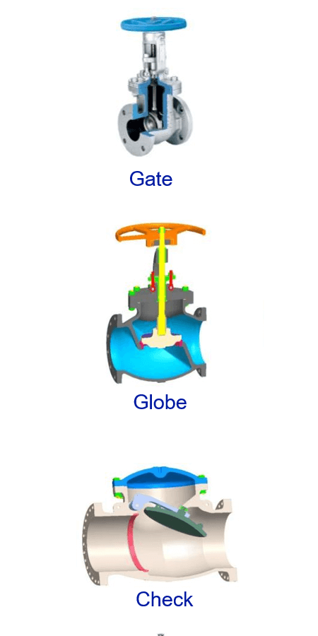
Gate valves
Gate valves are named after the shape of the closure member, which resembles like a gate. The gate or disc as it is called, moves perpendicular to the direction of the flow and slides down to shut off the flow. These valves are isolation valves used for full shut off or full flow. The fluid flows through a gate valve in a straight-line with minimum pressure drop. The main advantage with gate valves is that it provides robust sealing and is used extensively in almost all industries.
Globe valves
Globe valves are named after their shape of the body, which resembles like a globe. The disc has a convex or plug profile and is lowered onto a matching annular seat located at the center of the valve. The opening between the disc and the seat is proportional to the travel of the disc, which gives globe valves good throttling capability. Globe valves are regulating valves used for throttling of the fluid flow. The fluid changes direction when flowing through a globe valve, and hence the pressure drop inside the valve is high.
Check valves
Check valves are used to ensure that the flow of fluid in one direction only. These valves are automatic valves, which open with forward flow and close against the reverse flow. These valves are also called non-return valves and are used for applications where unidirectional flow is required.
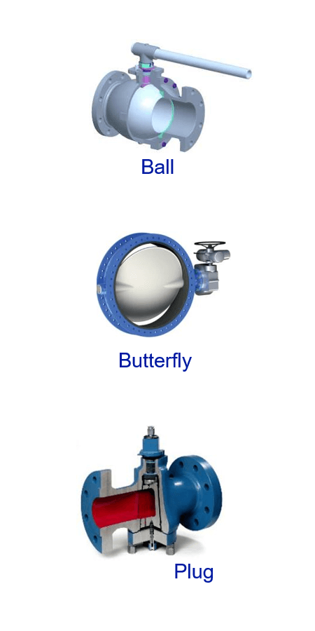
Ball valves
As the name implies, ball valves use ball shaped closure member to start or stop the fluid flow. The ball has a hole through it. When the hole of the ball is inline with the pipeline axis, the flow takes place and when it is rotated through 90 degrees the flow stops. Ball valves are widely used in chemical industry because of its ease of operation and high flow capacity.
Butterfly valves
Butterfly valves are rotary valves, used for both On-Off and throttling services. Butterfly valve has circular plate attached to shaft resembling wings of the butterfly, hence the name. The flow is controlled by the disc with its pivot axis at right angle to the direction of flow in the pipe. Butterfly valves are widely used in water supply and wastewater treatment applications.
Plug valves
Plug valves use plug shaped closure member to start or stop the fluid flow. The plug has a hole through it. When the hole of the plug is inline with the pipeline axis, the flow occurs and when it is rotated through 90 degrees the flow stops. Plug valves are basically used for starting and stopping of the fluid flow.
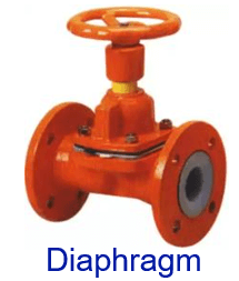
Diaphragm Valves
In diaphragm valves, the flexible body section is provided by diaphragm, which in connection with the compressor represents the closure member. When the compressor is lowered by the valve stem into a weir, the diaphragm seals and cuts off flow. Diaphragm valves are suitable for handling of corrosive fluids, fibrous slurries, radioactive fluids, or other fluids that must remain free from contamination. These valves are used for both ON-OFF and throttling services.
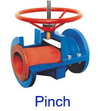
Pinch Valves
The pinch valve has a flexible tube inside the body, which is pinched either mechanically or by the application of air pressure to close the valve. Pinch valves provide smooth fluid flow without crevices and moving parts. The soft tube has also the ability to seal around the trapped solids. Pinch valves are ideally suited for handling of slurries, liquids with large amounts of suspended solids and are used for both ON-OFF and throttling services.
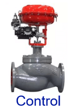
Control Valves
Control valves are power operated valves which modify the fluid rate in process control systems. Control valves are connected to actuator mechanism that are capable of changing the position of flow controlling element in the valves in response to signals from the controlling system. This enables the direct control of flow rate and the consequential control of process quantities such as pressure, temperature, and liquid level.
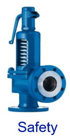
Pressure Relief Safety Valves
Pressure relief safety valves are designed to provide protection from over pressure in steam, gas, air and liquid lines. These valves release excessive pressure when pressure inside the valves exceeds the safe limit and close again when the pressure drop to preset limit.
Component of Valves
Regardless of types, all valves have the following basic parts
Body
The body forms the primary pressure boundary of a valve and holds all the components in position. Most of the valves require an opening across the body to assembly the closure member, seat and other parts inside the valve. In order to assembly all these parts the body is partitioned to provide an opening.
Bonnet
The cover for the opening in the valve body is the bonnet. The bonnet is the second principal pressure boundary of a valve. It is cast or forged of the same material as the body and is connected to the body by a threaded, bolted, or welded joint. In check valve, it is called as cover.
Valve Trim
The sealing components of valve are called as trim of the valves. They consists of seat, closure member and stem. These components requires higher hardness, corrosion and erosion resistant properties to give long trouble-free performance of valves.
Seat
The valve seat provides seating surface to the closure member. They are mounted on the upstream and downstream side of the valve. When the valve is closed, the closure member comes in contact with the seat to provide leak tight sealing.
Closure member
Based on the valve design the closure member of the valve can be a disc, ball, plug etc. The closure member is used to block the flow of fluid through the valve either partially or fully depending on the service application.
Stem
The stem is the component, which transmits the torque from the operator to the closure member. One end of the stem is connected to the closure member and the other end is connected to the device, which generates the torque necessary to operate closure member.
Gasket
Gasket is used in the joint between body and bonnet/cover of the valve. Different types of gasket are used – corrugated, spiral-wound, ring joint gasket, etc.
Packing
The set of packing rings are used to seal the area of the stem where it protrudes from the bonnet. Graphite is popularly used as packing materials.
Operating Mechanism
Valves start, stop or regulate the flow in piping systems. These duties are performed by adjusting the position of the closure member in the valve. This can be done either manually or automatically. If the closure member is moved linearly, then those valves are called linear valves. As the linear valves require multiple turns of handwheel, they are also called as multi-turn valves. If the closure member is rotated 90 deg, then those valves are called rotary valves or quarter-turn valves. Some of valves are self-operating i.e. the reversal of flow and excess pressure automatically operate the valves. E.g.: Check Valves and Pressure Relief Safety Valves.
Manual Operation
Most of the valves are manually operated. Multi-turn valves are operated by handwheel. Quarter-turn valves are operated by lever or wrench. For ease of operation, the operating force is normally restricted to 360 N.
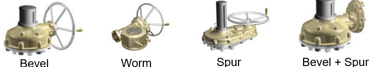
Gear operation
For larger sizes or high pressure valves, the operating force required is much more than 360 N. To reduce the operating force, gear box is used. The mechanical advantage available in the gear box helps reduce the operating force. However the number of turns required to operate the valve increases by gear ratio of the gear box. Various types of gear boxes are used – bevel, worm, spur and combination of these types. Nowadays, gear boxes used on valves are specially made suitable for directly mounting on valves with suitable travel stop as well as position indicator.
Power Operation
There are many occasions when the valve operation needs to be automated. The requirements may rise from fast operation, sequential operation, frequent operation or when the valves are located in remote or hazardous locations. It is also required when fail-safe mode needs to be achieved. There are different types of actuators available:
Actuators
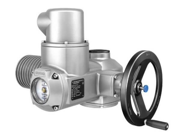
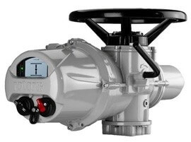
Electric Actuators
The electric actuator has a motor drive that provides torque to operate a valve. Electric actuators are frequently used on multi-turn valves such as gate or globe valves. With the addition of a quarter turn gearbox, they can be utilized on ball, plug or other quarter turn valves. Nowadays electric actuators specially made for valves with many in-built control systems – torque, position, remote indication, manual override, etc. They are also available for different power supply conditions – voltage (AC or DC), phase, frequency, etc.
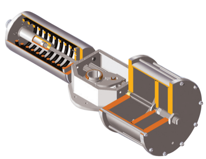
Pneumatic actuators
These actuators are popularly used as air is easily available in any industry. There are various types of pneumatic actuators - rack-and-pinion, scotch-yoke, canted scotch-yoke, etc. Based on the construction, the output torque characteristics of the actuator change considerably. By adding a spring pack, fail safe mode can be easily achieved. Linear pneumatic actuators are also available suitable for gate or globe valves. They can be piston or diaphragm type actuators.
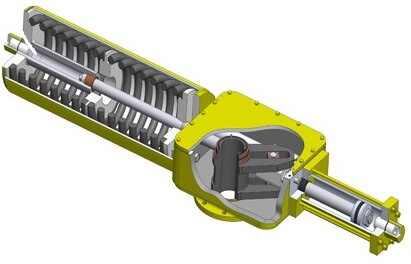
Hydraulic actuators
When the torque requirement of valve is high or when compact actuator is required, hydraulic actuators are used. There are various types of hydraulic actuators - double acting, scotch-yoke, canted scotch-yoke, etc. Based on the construction, the output torque characteristics of the actuator change considerably. By adding a spring pack, fail safe mode can be easily achieved. Linear hydraulic actuators are also available suitable for gate or globe valves. They are normally piston type actuators.
Codes and Standards
There are many international codes and standards applicable to valves and actuators. Good amount of technical requirements are given in these standards. The popular institutes are given below:
| Institute | Abbreviation | Website |
|---|---|---|
| American Petroleum Institute | API | api.org |
| American Society of Mechanical Engineers | ASME | asme.org |
| American Society for Testing and Materials | ASTM | astm.org |
| American Water Works Association | AWWA | awwa.org |
| American National Standards Institute | ANSI | asni.org |
| Manufacturers Standardization Society | MSS | mss-hg.org |
| American Welding Society | aws | aws.org |
| British Standards Institute | BSI | bsigroup.com |
| Bureau of Indian Standards | BIS | bis.org.in |
| International Organization for Standardization | ISO | iso.org |
| National Association of Corrosion Engineers | NACE | nace.org |
| Deutsches Institut für Normung | DIN | din.de |
Conclusion
In this section, simple basic principles of valves and actuators are described. However in each type of valves or actuators, there are innumerable variations available. For example, in gate valves, there are variations like solid disc, flexible disc, parallel slide, double disc, expanding disc, slab disc, etc. It is highly recommended to recognize the possible variations and select the correct type based on recommendations from valve manufacturers or valve experts.